- 您现在的位置:买卖IC网 > Sheet目录1210 > DK-414N-4 (Luminus Devices Inc)KIT DEV PHLATLIGHT CBM380 LED
�� �
�
�DK-� 414N-� 4� Development� Kit� Manual�
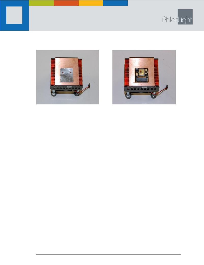
�2.� The� heat� sink� surface� must� be� free� of� dust� particles.� Place� the� thermal� interface� sheet� on� the� heat� sink�
�with� its� pre-drilled� holes� matching� the� holes� on� the� heat� sink� (Figure� 8).�
�Figure� 8:� Thermal� interface� sheet� on� heat� sink�
�Figure� 9:� Device� mounted� on� heat� sink�
�3.� Place� the� device� on� the� thermal� interface� sheet.�
�4.� Insert� screws� in� the� holes� of� the� coreboard� and� tighten.� To� ensure� equal� pressure� is� exerted� by� all�
�screws,� alternate� tightening� each� screw� until� the� board� is� securely� fastened.� The� device� is� now� mounted�
�and� ready� for� electrical� connections� (Figure� 9).�
�3.3� Electrical� Connections�
�The� following� sections� assume� that� the� user� has� all� the� equipment� listed� in� Table� 1.�
�1.� Each� of� the� four� LEDs� in� the� CBM� 380� can� be� driven� at� 9-12� A� and� the� power� supply� being� used� must� be�
�capable� of� providing� sufficient� power� to� drive� the� CBM-380.� Preset� the� output� voltage� to� 0� V� and� keep�
�the� power� supply� switched� off� until� all� connections� are� established.�
�2.� Connect� the� driver� boards� to� the� LED� and� the� power� supply� using� the� cables� provided� in� the� kit� (Figure�
�10).� Consult� Appendix� F� for� the� LED� electrical� pin-out� to� determine� which� color� each� driver� board� would�
�be� controlling.� The� driver� board� to� LED� cable� connects� to� the� driver� boards� at� P10� and� has� thermistor�
�connections� from� the� LED,� which� can� be� connected� to� test� points� THRM1� and� THRM2� on� any� driver�
�board,� if� necessary.� The� short� 2-pin� fan� cable� must� be� connected� to� one� of� the� driver� boards� at� J10.�
�3.� Use� the� jumper� provided� with� the� driver� board� to� short� signal� pins� 2� and� 3� (see� Figure� 1� and� Table� 5).�
�These� pins� correspond� to� Analog� ADJ� and� POT;� shorting� them� enables� the� on-board� potentiometer.�
�Alternatively,� the� jumper� can� be� removed� and� signal� cable� can� be� used� to� short� the� Analog� ADJ� and�
�POT� pins.�
�4.� Set� the� POTs� to� the� minimum� current� setting� by� rotating� them� fully� counter-clockwise.� The� embedded�
�arrow� should� point� towards� the� “10”� on� the� POT.�
�5.� The� development� kit� is� now� ready� to� be� powered� on.� Turn� on� the� power� supply� and� increase� the� source�
�voltage� to� -12� V.� The� driver� will� draw� about� 1-2� A� current.�
�CAUTION:� Do� not� set� the� power� supply� higher� -12� V;� doing� so� may� damage� the� driver.�
�960031� Rev� C� ?� Luminus� Devices,� Inc.� All� rights� reserved.�
�Page� 6�
�发布紧急采购,3分钟左右您将得到回复。
相关PDF资料
DK-PS21765
KIT DEV INTERFACE IPM MINIDIP
DK-PS21965
KIT DEV INTERFACE IPM MINIDIP
DK-RV-1.8-TRK-33
EVAL KIT SQUIGGLE MOTOR + SENSOR
DK-SI-4S100G2N
KIT DEV STRATIX IV TRANSCEIVER
DLP-2232H
MODULE USB ADAPTER FOR FT2232H
DLP-2232ML-G
MODULE USB ADAPTR FOR FT2232D LP
DLP-2232MSPF
MODULE USB ADAPTER WITH MCU
DLP-CB-DLPC200-10R
BOARD CONTROLLER FOR DLP
相关代理商/技术参数
DK-420-165
制造商:Avdel 功能描述:
DK42GY
功能描述:电气外壳 RoHS:否 制造商:Bud Industries 产品:Wall Mount Enclosures 类型:Single Door NEMA 额定值:3R 外部深度:254 mm 外部高度:305 mm 外部宽度:305 mm 面板宽度:261 mm 面板高度:261 mm 材料:Steel 颜色:Gray 通风:Not Available
DK42LG
功能描述:电气外壳 RoHS:否 制造商:Bud Industries 产品:Wall Mount Enclosures 类型:Single Door NEMA 额定值:3R 外部深度:254 mm 外部高度:305 mm 外部宽度:305 mm 面板宽度:261 mm 面板高度:261 mm 材料:Steel 颜色:Gray 通风:Not Available
DK431
功能描述:LCD DPM +5V 200MV 3.5 DIGIT -GRN RoHS:是 类别:工业控制,仪表 >> 仪表 - 面板,数字 系列:DK100/300 标准包装:12 系列:* 其它名称:Q7072030
DK432
功能描述:LCD DPM +5V 2V 3.5 DIGIT -GREEN RoHS:是 类别:工业控制,仪表 >> 仪表 - 面板,数字 系列:DK100/300 标准包装:12 系列:* 其它名称:Q7072030
DK-43WQH-1788
功能描述:显示开发工具 4.3" WQVGA TOUCH LCD KIT FOR LPC1788
RoHS:否 制造商:4D Systems 产品:4Display Shields 工具用于评估:?OLED-160-G1, ?OLED-160-G2 接口类型:Serial 工作电源电压:5 V
DK-43WQT-RX63N
制造商:Future Designs Inc (FDI) 功能描述:KIT 4.3" LCD TOUCH FOR RX63N
DK44-1.0
制造商:YAMAICHI 制造商全称:Yamaichi Electronics Co., Ltd. 功能描述:1.0mm High Density FLEX (300V, 105°C)